User:Qef/Orthographic hypercube diagrams
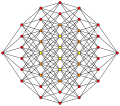
The code below was used to create all of the following SVG diagrams, which show n-dimensional hypercubes (a square or cube extruded into n dimensions), with the vertices projected onto a two-dimensional plane with an orthographic projection:
-
 2-cube
 -
 3-cube
 -
 4-cube
 -
 5-cube
 -
 6-cube
 -
 7-cube
 -
 8-cube
 -
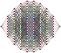 9-cube
 -
 10-cube


These SVG images were created to replace bitmap GIF versions created by Tom Ruen (User:Tomruen). See his description of how the originals were made here.
The Lua program below was used to create the SVG images. To recreate them, set the DIM value to the number of dimensions of the cube and run the program.
I'm hereby placing this program into the public domain. Do what you want with it. If it breaks, you get to keep both pieces.
This program requires the Lua matrix module to be installed.
local DIM = 3

local SCALE, VERTEX_RADIUS, MARGIN = 185, 5, 5

local STROKE_COLOUR = "#000"
local STROKE_WD_MAX, STROKE_WD_INCR = 1.3, 0.05
local VERTEX_COLOUR = {
    '#fc0204',  -- red
    '#fc7e04',  -- orange
    '#fcfe04',  -- yellow
    '#7cfe04',  -- redish green
    '#04fe04',  -- green
    '#04fe7c',  -- blueish green
    '#04fefc',  -- lt blue
    '#047efc',  -- md blue
    '#0402fc',  -- dk blue
    '#7c02fc',  -- purple
    '#fc02fc',  -- lt purple
}

local Matrix = require "matrix"

function is_bit_set (n, bitnum)
    for _ = 1, bitnum - 1 do n = math.floor(n / 2) end
    return n % 2 == 1
end

function set_bit (n, bitnum)
    if not is_bit_set(n, bitnum) then n = n + 2 ^ (bitnum - 1) end
    return n
end

function hypercube_vertices ()
    local h = {}
    for i = 0, 2 ^ DIM - 1 do
        local v = {}
        for j = 1, DIM do v[j] = is_bit_set(i, j) and 0.5 or -0.5 end
        h[i + 1] = v
    end
    return h
end

function scale_to_unit_vector (v)
    local m = 0
    for _, x in ipairs(v) do m = m + x * x end
    m = 1 / math.sqrt(m)
    for i, x in ipairs(v) do v[i] = m * x end
end

function vector_add_and_mul (v1, v2, m)
    for i, x in ipairs(v1) do v1[i] = x + v2[i] * m end
end

function vector_dot_product (v1, v2)
    local r = 0
    for i = 1, #v1 do r = r + v1[i] * v2[i] end
    return r
end

-- Given two basis vectors, solve the equations for the plan to find the
-- x and y coordinates on the plane's two dimensional space.
function vector_to_plane_pos (xb, yb, v)
    local coordmat = {}
    for i = 1, DIM do
        local row = { xb[i], yb[i] }
        for j = 3, DIM do row[j] = i == j and 1 or 0 end
        row[DIM + 1] = v[i]
        coordmat[i] = row
    end
    coordmat = Matrix:new(coordmat)
    assert(Matrix.dogauss(coordmat), "couldn't solve coordinate equations")
    return coordmat[1][DIM + 1], coordmat[2][DIM + 1]
end

function round_to_int (n)
    local f = n % 1
    return (f >= 0.5) and (n - f + 1) or (n - f)
end

local cube = hypercube_vertices()

-- First basis vector.
local view1 = {}
for k, v in pairs(cube[1]) do view1[k] = v end
scale_to_unit_vector(view1)

-- Second basis vector.
local view2 = {}
for i = 1, DIM do view2[i] = 0 end
local v = 1
for i = 1, DIM do
    vector_add_and_mul(view2, cube[v], 1)
    v = v * 2
end
vector_add_and_mul(view2, view1, -vector_dot_product(view2, view1))
scale_to_unit_vector(view2)

-- Projection matrix for othrographic projection onto the plane containing
-- the vectors view1 and view2.
local A = {}
for i = 1, DIM do
    local u = {}
    u[1] = view1[i]
    u[2] = view2[i]
    A[i] = u
end
A = Matrix:new(A)
local AT = Matrix.transpose(A)
local P = A * AT

-- Project vertices into 2D space.  They are rounded to integer coordinates
-- so that ones on top of each other can be combined without floating point
-- errors getting in the way.
local vert = {}
local max_x, max_y = 0, 0
for i = 1, #cube do
    -- Project n-dimensional coordinate onto n-dimensional plane.
    local vmat = {}
    for j = 1, DIM do vmat[j] = { cube[i][j] } end
    vmat = P * Matrix:new(vmat)
    -- Find 2-dimensional coordinate on plane.
    local x, y = vector_to_plane_pos(view1, view2, Matrix.transpose(vmat)[1])
    x = round_to_int(x * SCALE)
    y = round_to_int(y * SCALE)
    vert[i] = { x, y }
    -- Find bounds of vertex positions in output.
    if x > max_x then max_x = x end
    if y > max_y then max_y = y end
end

-- Calculate final image size and translate vertices so that they are centered
-- in the image and all have positive coordinates.
local halfwd = max_x + VERTEX_RADIUS + MARGIN
local halfht = max_y + VERTEX_RADIUS + MARGIN
for _, v in ipairs(vert) do
    v[1] = v[1] + halfwd
    v[2] = v[2] + halfht
end

-- Collect vertices which appear on top of each other in the output, and
-- prepare an array of vertices to be drawn, with a count of how many actual
-- vertices are represented by one dot in the image.
local distinct_vert = {}
for _, v in ipairs(vert) do
    local x, y = unpack(v)
    local already_added = false
    for _, w in ipairs(distinct_vert) do
        if w[1] == x and w[2] == y then
            w[3] = w[3] + 1
            already_added = true
            break
        end
    end
    if not already_added then
        distinct_vert[#distinct_vert + 1] = { x, y, 1 }
    end
end

-- Write SVG file.
local fh = assert(io.open(DIM .. "-cube_column_graph.svg", "wb"))
fh:write('<?xml version="1.0" encoding="UTF-8"?>\n',
         '<svg version="1.0" width="', halfwd * 2,
         '" height="', halfht * 2, '"',
         ' xmlns="http://www.w3.org/2000/svg">\n',
         ' <g stroke="', STROKE_COLOUR, '" fill="none">\n')

-- Draw edges.  First they are collected in a table so that the ones which
-- appear on top of each other can be drawn with a single line, which allows
-- the style to be adjusted for overlayed lines, and is more efficient than
-- drawing them all individually.
local edges = {}
for n1 = 0, #vert - 1 do
    local x1, y1 = unpack(vert[n1 + 1])
    for axis = 1, DIM do
        if not is_bit_set(n1, axis) then
            local n2 = set_bit(n1, axis)
            local x2, y2 = unpack(vert[n2 + 1])
            local pathseg = "M" .. x1 .. "," .. y1 .. "L" .. x2 .. "," .. y2
            edges[pathseg] = (edges[pathseg] or 0) + 1
        end
    end
end
-- Build single SVG path for each number of overlayed edges, and find the
-- largest number of edges which appear as a single line.
local count_edges, max_edges_count = {}, 1
for pathseg, count in pairs(edges) do
    count_edges[count] = (count_edges[count] or "") .. pathseg
    if count > max_edges_count then max_edges_count = count end
end
-- Write SVG paths for edges.
for count, path in pairs(count_edges) do
    local edge_wd = STROKE_WD_MAX - (max_edges_count - count) * STROKE_WD_INCR
    fh:write('  <path stroke-width="', edge_wd, '" d="', path, '"/>\n')
end

-- Write SVG for vertices.
for _, v in ipairs(distinct_vert) do
    local x, y, count = unpack(v)
    --if count > #VERTEX_COLOUR then count = #VERTEX_COLOUR end
    count = (count - 1) % #VERTEX_COLOUR + 1
    assert(VERTEX_COLOUR[count], "no style for vertex count " .. count)
    fh:write('  <circle cx="', x, '" cy="', y, '" r="', VERTEX_RADIUS, '"',
             ' fill="', VERTEX_COLOUR[count], '"/>\n')
end

fh:write(' </g>\n',
         '</svg>\n')
This program is all my own work, except that the calculations to figure out the two vectors to use as a basis for the projection (view1 and view2) were derived from the Delphi code used to create the original GIF versions of these diagrams. This is the only piece of the Delphi source I've seen:
begin
  view1.copy(dim,cube.vert[1]);
  view1.scaleunit;
  view2.init(dim);
  v:=1;
  for i:=1 to dim do begin
    view2.add(cube.vert[v],1);
    v:=v*2;
    end;
  end;
  view2.add(view1,-view2.dot(view1)); // force view2 perpendicular to view1
  view2.scaleunit;
end;<ref>
</ref><ref><ref></ref></ref>